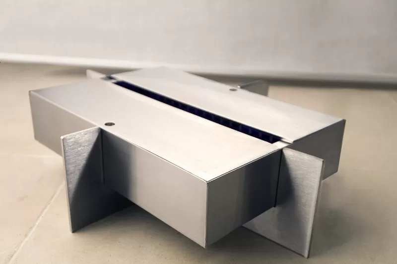
Services

CAD/CAM Design
1. As a specialized sheet metal fabrication company, SHARP CENTURY provides 2D and 3D drawing creation.
2. Optimize flat pattern development (considering bend factors and material utilization).
3. DFM (Design for Manufacturability): Evaluate design rationality to avoid manufacturing difficulties.

Rapid Prototyping
1. Validate design feasibility through sheet metal processing or 3D printing.
2. Small batch trial production (to verify processes and assembly).
Services
Sheet metal processing is a manufacturing process that involves transforming metal sheets into desired components through processes such as cutting, bending, stamping, and welding. Below is a description of the standard sheet metal processing workflow:
Design and Process Planning: CAD design and Design for Manufacturability (DFM) analysis.
Material Preparation: Material selection → Sheet cutting.
Forming Processes: Bending; Stamping; Rolling.
Joining Processes: Welding; Riveting.
Surface Treatment: Painting; Plating; Brushing/Polishing, etc.
Quality Inspection: Dimensional inspection; Functional testing.
Sharp Century's advanced sheet metal prototype service provides superior metal components tailored to your needs.

Services
Common Issues and Solutions in Sheet Metal Manufacturing:
Why does warping occur during sheet metal bending, and how can it be prevented?
Warping often happens due to uneven stress distribution during the bending process. It can be caused by improper material handling, inaccurate tooling setup, or inconsistent thickness. To prevent warping, ensure uniform material thickness, use the correct V-die size and punch radius, and apply precise bending force. Using simulation software can also help predict and eliminate potential warping issues before production.
What causes burrs on cut edges, and how can they be minimized?
Burrs are rough edges or protrusions formed during cutting, typically due to worn-out tools, incorrect cutting speed, or unsuitable die clearance. To minimize burrs, regularly maintain cutting tools, adjust cutting parameters based on material type and thickness, and ensure appropriate die clearance. Laser or waterjet cutting methods can also significantly reduce burr formation compared to mechanical cutting.
Why do cracks appear during deep drawing, and how can they be avoided?
Cracks during deep drawing usually result from excessive material stress, improper lubrication, or using material with poor ductility. To avoid this, choose high-quality, ductile sheet metal, apply proper lubrication to reduce friction, and optimize the punch and die design for smooth material flow. Gradual forming with intermediate annealing steps may also help when working with more challenging materials.